It is a non-destructive testing (NDT) method in which beams of high frequency sound waves that are introduced into the material being tested are used to detect surface and sub-surface flaws. The sound waves travel through the materials with some attenuation of energy and are reflected at interfaces. The reflected beam is detected and analyzed to define the presence and location of flaws. Cracks, laminations, shrinkage, cavities, bursts, flakes, pores, bonding faults and other discontinuities can be easily detected. Inclusions and other in homogeneities in the metal being inspected can also detected by causing partial reflection or scattering of the ultrasonic waves, or by producing some other detectable effect on the ultrasonic waves.
- Ultrasonic Testing (UT)
- UT Techniques:Straight Beam
- Angle Beam
- Immersion Testing
- Through Transmission
- Phased Array
- Time of Flight Diffraction
- ADVANTAGES :
- LIMITATIONS :
Ultrasonic Testing (UT)
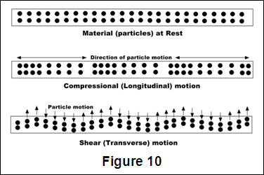
Ultra-high frequency sound is introduced into the part being inspected and if the sound hits a material with different acoustic impedance (density and acoustic velocity), some of the sound will reflect back to the sending unit and can be presented on a visual display. By knowing the speed of the sound through the part (the acoustic velocity) and the time required for the sound to return to the sending unit, the distance to the reflector (the indication with the different acoustic impedance) can be determined. The most common sound frequencies used in UT are between 1.0 and 10.0 MHz, which are too high to be heard and do not travel through air. The lower frequencies have greater penetrating power but less sensitivity (the ability to "see" small indications), while the higher frequencies don't penetrate as deeply but can detect smaller indications.
Sound is introduced into the part using an ultrasonic transducer ("probe") that converts electrical impulses from the UT machine into sound waves, then converts returning sound back into electric impulses that can be displayed as a visual representation on a digital or LCD screen (on older machines, a CRT screen). If the machine is properly calibrated, the operator can determine the distance from the transducer to the reflector, and in many cases, an experienced operator can determine the type of discontinuity (like slag, porosity or cracks in a weld) that caused the reflector. Because ultrasound will not travel through air (the atoms in air molecules are too far apart to transmit ultrasound), a liquid or gel called "couplant" is used between the face of the transducer and the surface of the part to allow the sound to be transmitted into the part.
UT Techniques : Straight Beam
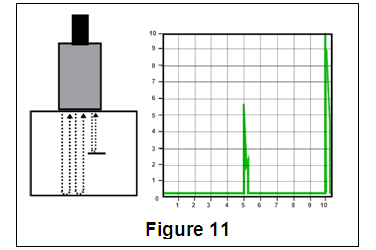
Straight beam inspection uses longitudinal waves to interrogate the test piece as shown at the right. If the sound hits an internal reflector, the sound from that reflector will reflect to the transducer faster than the sound coming back from the back-wall of the part due to the shorter distance from the transducer. This results in a screen display like that shown at the right. Digital thickness testers use the same process, but the output is shown as a digital numeric readout rather than a screen presentation.
Angle Beam
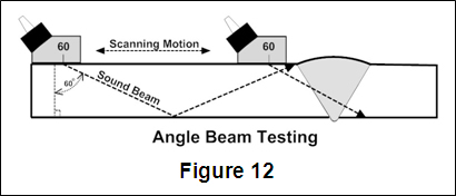
Angle beam inspection uses the same type of transducer but it is mounted on an angled wedge (also called a "probe") that is designed to transmit the sound beam into the part at a known angle. The most commonly used inspection angles are 45o, 60o and 70o, with the angle being calculated up from a line drawn through the thickness of the part (not the part surface). If the frequency and wedge angle is not specified by the governing code or specification, it is up to the operator to select a combination that will adequately inspect the part being tested.
In angle beam inspections, the transducer and wedge combination (also referred to as a "probe") is moved back and forth towards the weld so that the sound beam passes through the full volume of the weld. As with straight beam inspections, reflectors aligned more or less perpendicular to the sound beam will send sound back to the transducer and are displayed on the screen.
Immersion Testing
Immersion Testing is a technique where the part is immersed in a tank of water with the water being used as the coupling medium to allow the sound beam to travel between the transducer and the part. The UT machine is mounted on a movable platform (a "bridge") on the side of the tank so it can travel down the length of the tank. The transducer is swivel-mounted on at the bottom of a waterproof tube that can be raised, lowered and moved across the tank. The bridge and tube movement permits the transducer to be moved on the X-, Y- and Z-axes. All directions of travel are gear driven so the transducer can be moved in accurate increments in all directions, and the swivel allows the transducer to be oriented so the sound beam enters the part at the required angle. Round test parts are often mounted on powered rollers so that the part can be rotated as the transducer travels down its length, allowing the full circumference to be tested. Multiple transducers can be used at the same time so that multiple scans can be performed.
Through Transmission
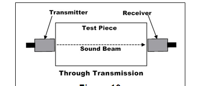
Through transmission inspections are performed using two transducers, one on each side of the part. The transmitting transducer sends sound through the part and the receiving transducer receives the sound. Reflectors in the part will cause a reduction in the amount of sound reaching the receiver so that the screen presentation will show a signal with lower amplitude (screen height).
Phased Array
Phased array inspections are done using a probe with multiple elements that can be individually activated. By varying the time when each element is activated, the resulting sound beam can be "steered", and the resulting data can be combined to form a visual image representing a slice through the part being inspected.
Time of Flight Diffraction
Time of Flight Diffraction (TOFD) uses two transducers located on opposite sides of a weld with the transducers set at a specified distance from each other. One transducer transmits sound waves and the other transducer acting as a receiver. Unlike other angle beam inspections, the transducers are not manipulated back and forth towards the weld, but travel along the length of the weld with the transducers remaining at the same distance from the weld. Two sound waves are generated, one travelling along the part surface between the transducers, and the other travelling down through the weld at an angle then back up to the receiver. When a crack is encountered, some of the sound is diffracted from the tips of the crack, generating a low strength sound wave that can be picked up by the receiving unit. By amplifying and running these signals through a computer, defect size and location can be determined with much greater accuracy than by conventional UT methods.
ADVANTAGES :
• It is sensitive to both surface and subsurface discontinuities.
• The depth of penetration for flaw detection or measurement is superior to other NDT methods.
• Only single-sided access is needed when the pulse-echo technique is used.
• It is highly accurate in determining reflector position and estimating size and shape.
• Minimal part preparation is required.
• Electronic equipment provides instantaneous results.
• Detailed images can be produced with automated systems.
• It has other uses, such as thickness measurement, in addition to flaw detection.
LIMITATIONS :
• Surface must be accessible to transmit ultrasound.
• Skill and training is more extensive than with some other methods.
• It normally requires a coupling medium to promote the transfer of sound energy into the test specimen.
• Materials that are rough, irregular in shape, very small, exceptionally thin or not homogeneous are difficult to inspect.
• Cast iron and other coarse grained materials are difficult to inspect due to low sound transmission and high signal noise.
• Linear defects oriented parallel to the sound beam may go undetected.
• Reference standards are required for both equipment calibration and the characterization of flaws.